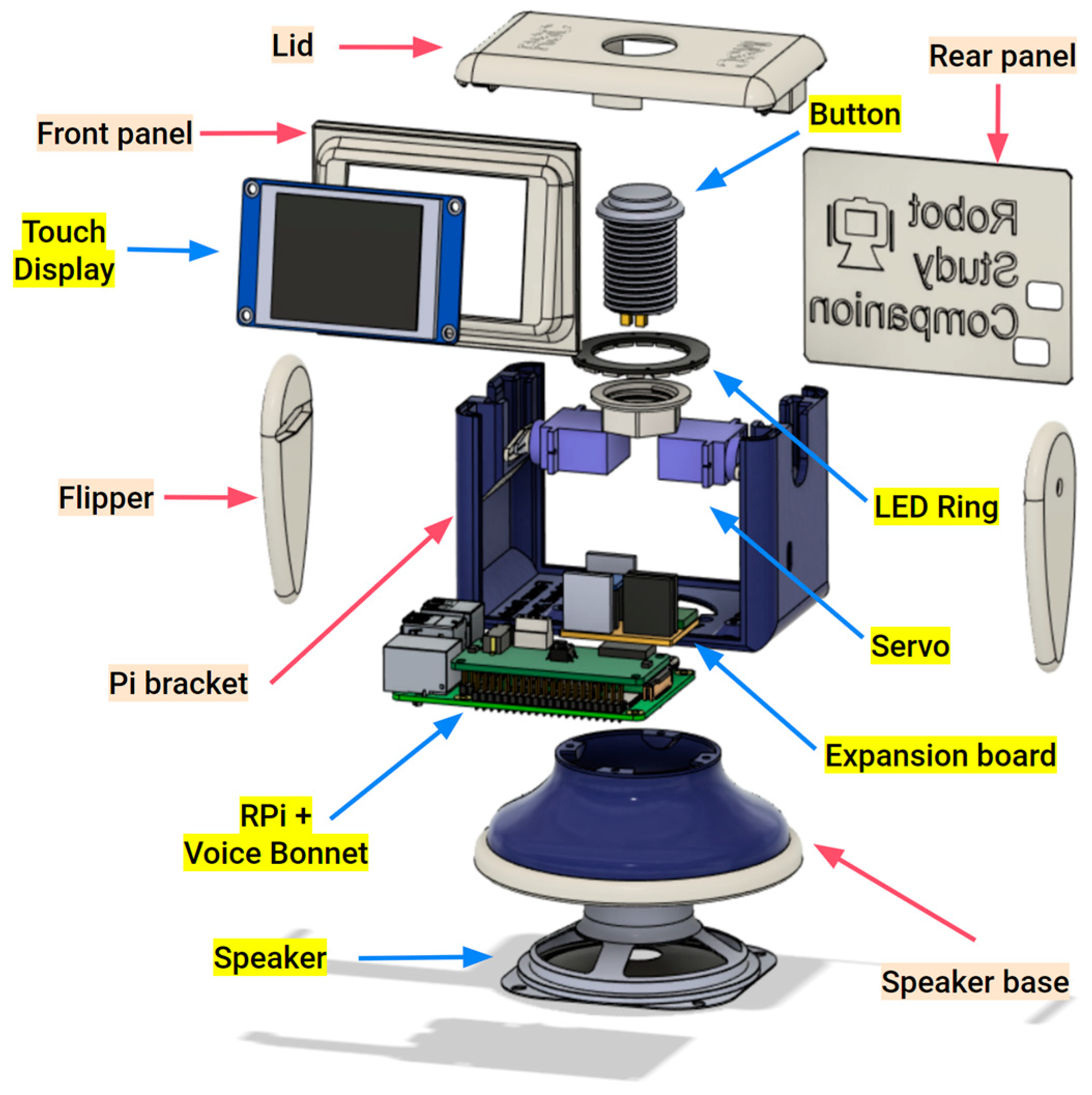
Please familiarise yourself with the components in the overview below:
This guide will walk you through each step of assembling the RSC v4.
Use the navigation buttons below to move through each of the assembly steps.
Step 02: Assembling the Base
Carefully place the loudspeaker in the base and rotate it to align with the mounting holes.
Make sure to route the speaker wire through the round top slot.
Position the base trim cover over the loudspeaker.
Align the parts then secure the subassembly with four M3x8mm fasteners.
See video below for more details:
By the end of this step, you will have assembled the base of the RSC v4.
Step 03: Connect the Pi Bracket to the Speaker Base
Position the main chassis (Pi bracket) on the speaker base.
Align the bracket and base with the mounting holes.
Secure the bracket to the base with four M3x8mm fasteners.
Make sure to carefully route the speaker wires through the round slot.
See video below for more details:
By the end of this step, you will have attached the Pi bracket to the base.
Step 04: Attach the Raspberry Pi to the Bracket
Prepare and insert your AIY flashed SD card to its slot on the Raspberry Pi
We recommend Raspberry Pi Imager (v1.7 or later) and enabling SSH and VNC for remote access.
Align your Raspberry Pi with the mounting holes in the Pi bracket.
Route the speaker wires through the gap between the Pi bracket and the Raspberry Pi.
Use four M2.5x6mm fasteners to secure the Raspberry Pi to the Pi bracket.
See video below for more details:
By the end of this step, you have installed the Raspberry Pi in the RSC v4.
Step 05: Connect the Expansion Board to the AIY Voice Bonnet (v2) HAT
Align the Voice Bonnet HAT with your Expansion Board by matching connector orientation.
Gently press both together until fully seated.
By the end of this step, you have installed the Expansion Board to the Voice Bonnet HAT.
Step 06: Install the Voice Bonnet HAT on the Raspberry Pi
Carefully align your Voice Bonnet HAT over the Raspberry Pi GPIO headers.
Press gently to install the HAT on the header pins.
See video below for more details:
By the end of this step, the Voice Bonnet HAT is on the Raspberry Pi.
Step 07: Connecting the Speaker Wires
You will need a precision screwdriver for this step.
Carefully plug your speaker wires into the screw terminal connector on the Voice Bonnet HAT.
Tighten the embedded fasteners to secure both speaker wires.
Make sure to keep the speaker wires from connecting to each other.
See video below for more details:
By the end of this step, you have connected your speaker to the Voice Bonnet HAT.
Step 08: Wiring the Expansion Board
Use jumper wires to connect Expansion Board's Level Shifter for peripheral communication.
Connect Raspberry Pi 3.3V GPIO to Expansion Board 3.3V connector.
Connect Raspberry Pi PWM GPIO to Expansion Board PWM connector.
Connect Voice Bonnet HAT TX and RX to Expansion Board TX and RX connectors.
See video below for more details:
By the end of this step, you wired up your Expansion Board Level Shifter.
Step 09: Inserting the Servo Motors
Insert the servo horn to the flipper horn socket.
Push the flipper with the servo horn onto the servo motor shaft.
Secure the flipper and horn to the motor shaft with the provided shaft fastener screw
Repeat for second flipper then gently push each motor to their slot in the Pi bracket.
The motors should slide in the slot with some resistance, depending on the printed part tolerance.
See video below for more details:
By the end of this step, you installed both flippers.
Step 10: Plugging the Motors in the Expansion Board
Connect the motors to the three pin PWM header pins on the Expansion Board.
Make sure the ground (GND; black/brown wire) aligns with the GND pin on the header.
See video below for more details:
By the end of this step, you have installed both flippers of your RSC v4.
Step 11: Connecting the Display to the Expansion Board
Plug the Display UART connector wires to their header on the Touch Display.
Plug the Display UART to the UART 5V header pins of the Level Shifter on the Expansion Board.
Make sure the connecter is firmly seated and the orientation matches the pin labels: 5V, TX, RX, GND.
See video below for more details:
By the end of this step, you connected the display.
Step 12: Fasten the Display to the Front Panel
Insert the Touch Display into the Front Panel frame, facing the opening slot.
Carefully fasten the Display to the frame using four M3x4mm screws, one for each corner.
Ensure the connector cable remains accessible at the back for routing into the chassis.
Make sure the Display is flush with the frame opening.
See video below for more details:
By the end of this step, you fastened your display to the front panel.
Step 13: Fit the Front Panel
Hold your Front Panel by the Raspberry Pi GPIO header and align it with the channel grooves in the Pi bracket.
Gently push your Front Panel down the channel grooves.
Make sure the Front Panel is flush with the Pi bracket with no pinched wires.
See video below for more details:
By the end of this step, you installed the face of your RSC v4.
Step 14: Assemble the Lid with Button and NeoPixel Ring
Push the Arcade button in the Lid opening.
Route the NeoPixel connector wires through the Button Nut.
Sit the NeoPixel LED ring around the Arcade Button shaft, on the shelf under the Lid, facing down.
Fasten the button and NeoPixel ring in place gently using the Button Nut.
Route the button wires and NeoPixel wires neatly so they remain accessible for connection to the Expansion Board.
See video below for more details:
By the end of this step, you assembled the lid.
Step 15: Connect the NeoPixels and Button
Connect the NeoPixel LED Ring wires (5V, GND, PWM signal) to its header pins on the Expansion Board.
Connect the Arcade Button wires to the AIY Voice Bonnet button header.
Note: Make sure to secure all connections and route wires carefully inside the chassis to help reduce interference when closing the lid.
See video below for more details:
By the end of this step, you connected the lid.
Step 16: Install the Rear panel and Lid
Align the Rear panel with the channel grooves at the back of the Pi bracket.
Gently push your Rear panel down the channel grooves until flush with the Pi bracket.
Carefully tidy all wires in the chassis to prevent pinching or interference when closing the Lid.
Align the Lid on the Pi bracket and gently press down until flush with the Pi bracket.
See video below for more details:
By the end of this step, you have fully assembled your RSC v4 😊🎉
Step 1 / 15
Version: RSC v4.1
Step 01: Assemble the Speaker Unit
Insert the Speaker into the Speaker Case, aligning it with the inner support ring. Then, place the Speaker Lid on top and press gently until it snaps into place.
The lid is designed with a precision friction-fit grip, eliminating the need for screws while ensuring a secure hold.
Step 02: Mount the Pi Bracket onto the Speaker Unit
Align the Pi Bracket with the upper section of the Speaker Unit, ensuring the speaker wires pass cleanly through the central opening.
Gently rotate the Pi Bracket into position until it locks into the designed grooves.
Step 03: Mount the Raspberry Pi into the Pi Bracket
Place the Raspberry Pi 4 onto the Pi Bracket, aligning the mounting holes with the standoffs. Secure it using 4 × M2×6 screws.
Step 3.1: Check Pi Bracket
Ensure that the board is oriented so that the USB ports and microSD card slot align with their dedicated openings in the chassis.
Step 04: Mount the AIY Voice Bonnet onto the Raspberry Pi
Align the AIY Voice Bonnet with the GPIO header of the Raspberry Pi 4 and gently press it down until it is fully seated.
Make sure all the pins are correctly aligned and inserted straight into the header to prevent bending or loose contact.
Step 05: Mount the RSC Expansion Board onto the AIY Voice Bonnet
Align the RSC Expansion Board with the pin headers on the AIY Voice Bonnet, ensuring all pins match their respective sockets. Gently press the board down until it sits evenly on top of the bonnet.
If the board doesn’t hold firmly in place, secure it with 1 × M2×6 screw at the mounting hole provided on the edge of the board. This will keep it stable and prevent loose contact during operation.
Step 06: Connect the Speaker Wires to the Voice Bonnet
Insert the Speaker wires (red and black) into the terminal block on the AIY Voice Bonnet. Ensure the red wire goes into the positive (+) terminal and the black wire into the negative (–) terminal.
Use a small screwdriver to gently tighten both screws, securing the wires firmly in place. Make sure there is no loose connection before continuing.
Step 07: Connect the Expansion Board to the AIY Voice Bonnet
Use jumper wires to connect the RSC Expansion Board with the AIY Voice Bonnet as shown below. Ensure that each pin is connected correctly and the wire connections are firm.
Match the pins carefully as follows:
3.3V to 3.3V
TX to TXD
RX to TXD
PWM to PWM
Double-check that the orientation and wire colors match on both ends to prevent reversed connections.
Step 08: Mount the Servo Motors and Connect Them to the Expansion Board
Insert both Servo motors into their designated slots on the Main Chassis. Make sure the servo shafts face outward for proper flipper movement.
Once positioned, connect each servo cable to the PWM header on the Expansion Board, following the correct pin orientation:
Left Servo to PWM1 to Brown = GND, Red = 5V, Orange = Signal
Right Servo to PWM2 to Brown = GND, Red = 5V, Orange = Signal
P.S. Don't FORGET to attach (with screws) the printed flippers to the servos before moving on
Step 09: Connect and Mount the ESP32-2432S028 Display
Connect Display Wires:
Attach one end of the 1x4P connector cable to the VIN, TX, RX, and GND pins of the ESP32-2432S028 Display.
Ensure firm connections to avoid loose contact during operation.
Mount the Display into Its Case:
Place the ESP32 Display module into the Front Panel Display Case, aligning the screen with the front opening.
Press gently until the board sits flush within the case.
Fit the case gently into the chassis.
Step 10: Connect to Expansion Board
Connect the other ends of the wires from the ESP32-2432S028 Display Pin to the RSC Expansion Board as follows:
VIN to 5V
TX to TX
RX to RX
GND to GND
Step 11: Assemble the Head Unit (Button + NeoPixel Ring + Lid)
Prepare Components:
Gather the Lid (top cover), Arcade Button (with LED wires), Button Holder Ring, and NeoPixel Ring.
Insert the Button:
Pass the Arcade Button wires through the central hole of the Lid from the top side.
Insert the button firmly into the hole until the threaded section is fully visible underneath.
Mount the NeoPixel Ring:
Pass the button wires through the center of the NeoPixel Ring and position the ring around the base of the button on the inner side of the Lid.
Align the ring with the small square supports inside the Lid; these ensure proper centering and stability.
Secure the Assembly:
Screw the white Button Holder Ring onto the base of the Arcade Button to lock the entire head unit (button + NeoPixel Ring) securely in place.
Step 12: Connect the NeoPixel Ring and Arcade Button
Connect the NeoPixel Ring:
Attach the NeoPixel Ring wires to the RSC Expansion Board.
Ensure the Signal (DIN) wire connects to the NeoPixel header pin on the Expansion Board.
The 5V and GND wires should connect to their respective power pins.
Connect the Arcade Button:
Plug the Arcade Button connector into the Button header on the AIY Voice Bonnet.
Step 13: Install the Power Switch and Rear Panel
Mount the Switch:
Insert the Power Switch into the rectangular slot on the Rear Panel from the back side. Push it in until it clicks into place; the fit is snug by design.
Attach the Rear Panel:
Carefully slide the Rear Panel into the Chassis, ensuring the switch wires pass neatly inside without being pinched.
Connect the Power Wires:
Plug the Power Switch wires into the Switch header on the RSC Expansion Board.
Step 14: Attach the Lid and Complete the Assembly
Position the Lid:
Carefully lower the Lid assembly (with the Arcade Button and NeoPixel Ring already installed) onto the top of the Chassis.
Ensure all internal wires are neatly tucked in to avoid being pinched.
Secure the Fit:
Gently press the Lid down until it snaps into place. The v4.1 design uses a precision friction-fit connection that holds the Lid securely without screws.
Final Check:
Confirm that:
The Arcade Button moves freely when pressed.
The Power Switch on the back panel toggles easily.
All seams are properly aligned for a clean finish.